Wiring
Introduction
Wiring is like programming or scripting. It enables you to program objects to do things to other objects. It enables you to handle events such as clicking on an object, or from timers that can be used to animate objects over time.
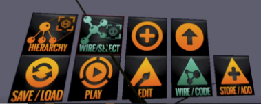
You can go into WIRE mode by choosing the WIRE/CODE menu item
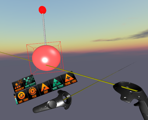
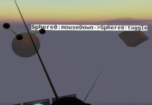
When you are in wire mode, you see a wiring "handle" and any existing green wired connections to other objects for anything you click on. For example, click on a sphere.
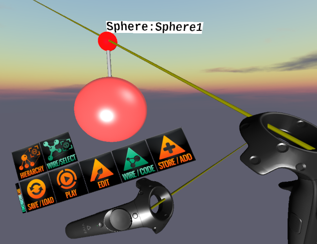
You see a ball and rod appear above the sphere. That is the wiring handle. A wiring "handle" looks like a red ball connected to an object by a bar, sort of like a chemistry molecular model.
Hover the ray over the ball to make a label appear saying what it is.
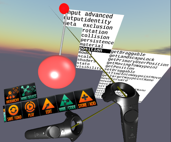
If you ray, click and release on the ball with the right controller trigger, that will bring up a menu of items (ports) that you can use to wire objects together.
Each object has an Input, Output and Meta menu.
- The Input menu lists methods that are fired when a message is received from another object.
- the Output menu lists messages that can be sent to other objects.
- The meta menu lists things you can do to the object while you are editing, such as Delete or Clone.
In the above image, the ray is pointing to an Input menu item: Position. This lists info about the object's position that can be requested.
Wiring to Another Object
Lets make a basic example using two objects. We are going to toggle the light on and off when the cube is clicked. Create a Cube and a Light. Aim the light at the cube. Click WIRE/CODE on the wrist menu. Now click on the Cube. You will see a wiring handle appear above the Cube.
PICTURE OF a Cube showing wiring handle.
Now click on the wiring ball for the Cube and select the output menu, and then drag to Events and then mouseUp. We are going to use the mouseUp event to tell the light to toggle on/off.
PICTURE of cube's output menu with mouseup selected.
A connecting wire will appear starting from the wiring handle's ball of the cube. drag the other end of it to the wiring handle ball for the light. Click on the ball. A menu will appear. Choose Input, and then Visibility and then click on "toggle".
'PICTURE of Light's Input menu with toggle selected. '
Now the mouseUp event from the cube is connected to the light's input to toggle visibility.
Point at the wire to see a popup label indicating what the wire does:
Click PLAY on the wrist menu and the wiring will disappear. Now you can click on the cube and it will toggle the light on and off.
To work on the wiring more, choose WIRE/CODE on the wrist menu, and the wiring will be shown again. If you want to delete a wire, click on the wire and choose delete from the meta menu that appears.
Outputs
Commonly used outputs include:
- Control
- ControlOut - this is usually wired to the controlIn input on another object.
- events
- mouseEntered - sent when the user's ray hovers over the object
- mouseDoubleClick - sent when the user double-clicks on the object
- mouseDown - sent when the user clicks on the object
- mouseExited - sent when the user's ray stops hovering over the object
- mouseUp - sent when the user stops the click on the object
- state
- positionChanged - sent when the position of the object changes
- propertyChanged - sent when a property changes
- rotationChanged - sent when the rotation changes
- scaleChanged - sent when the scale of the object changes
- position
- movedBy
- rotation
- rotatedBy
- collision
- collision
Inputs
Commonly used outputs include:
- control
- controlIn - usually connected to the controlOut of a controller object.
- visibility
- toggle - hide or show the object, switching it from its current state
- off - hide the object
- on - make the object visible
- getVisibility
- scale
- getScale
- setScale
- rotation
- getRotation
- setRotation - instantly rotates the object to the given rotation
- rotateBy - gradually rotates the object by a given rotation vector Parameters: (rotation, time)
- rotateTo - gradually rotates the object to a given rotation Parameters: rotation and time
- rotateAround (vector3f,float,int)
- rotateAroundYAxisBy - gradually rotates the object to an angle in a given time Parameters: (rotation, time)
- setPositionAndRotation (position, rotation)
- lookAt(vector3f)
- position
- getPosition
- setPosition - instantly moves the object to the given position
- moveBy - gradually moves the position by a given vector Parameters: position and time
- moveTo - gradually moves to a given position Parameters: position and time
- moveToWaypoint
- moveForward
- collision
- collisionEvent
- material
- getMaterial
- setMaterial
- setMaterialString
- setTextureLocator
Parameters
Some wiring requires extra information to complete the message to an object. This data is known as parameters. If a wire linking two wiring handle balls has a red ball in the middle, it needs parameters to be provided by more wires.
You have to get the value(s) for the required parameters from another object - typically that's a Variable type of object.
- Create a Non-Spatial EulerRandom object. That is an object that creates a random pitch, Yaw, Roll value that can be used to set an object's orientation (Rotation).
- Create a timer and a cube. We are going to make the cube rotate to a new oreintation every time the timer goes off (once per second)
- Click on the WIRE/CODE wrist menu. Click on the timer to make the wiring handle visible.
- Click on the wiring handle ball and choose the Output tick item. Tick sends a message every time the timer triggers.
- Drag the wire to the cube and a wiring handle will appear. Choose the Input State setRotation item. Now the timer is wired to the Cube's setRotation method.
- You will notice a red ball in the middle of the wire. That means you need to provide a parameter (a value that will be the new rotation).
- Click the red ball and choose the rotation item. Drag the wire to the EulerRandom object and choose the Input getValue. Now the EulerRandom object will provide a rotation parameter.
- You are done. Choose PLAY on the wrist menu and the cube should change its rotation every second.
Widgets
Widgets are object that the user can control things with. Thers include buttons and a slider.
Buttons, when clickedon, can send events that can be wired to trigger other objects.
The slider sends a changed numeric value when the user moves it.
Controllers
Controllers are objects that make controlling objects with wiring easier. You connect the output of a controller to the input of an object. For example, a controller outputs a position, that is wired to the input setPosition of an object you want to move. All Controllers have a ControlOut Output that is commonly wired to another object's ControlIn Input. This sends the information the controller is generating to the target object in a way that the object will know what to do, without you having to to know what exact setWhatever input to choose. See Moving_Objects_Along_Paths for more details on Controllers.
- RotationContoller2 – controls rotation
- EllipseMover2 – move things on ellipses or circles
- ScannerController2 – move things along a line one way or back and forth
- SineController2 – move things on Sine waves (with adjustable phase – so can do Sin, Cos or anything between)
- WaypointMover2 – moves things around on a path of waypoints
- LookAtController2 – look at things – i.e. giant eyeballs follow something you drag.
RotationController Example
Using a RotationController object makes wiring rotation easier.
There are the 3 properties for a RotationController:
- Interval - number of milliseconds between each step
- Steps - number of steps for rotation around the axis (e.g. 360 means one angular degree per step)
- Axis - the default is the Y axis - a vertical line through the center of the object
Say you want to rotate a planet. You wire the Output->ControlOut of a RotationController to the Input->ControlIn of the planet object. This passes the rotation data to the planet each time an interval has passed.
Remember this also applies to composites - you can always add stuff to a composite, offset the "satellite" from center and rotate the composite. Then both the planet and the satellite rotate.
Parameters and default values
menu = "input/rotation"
@ParmTypes(value = { @ParmType(name = "rotation", defaultValue="0,90,0"), @ParmType(name = "time", defaultValue="1000")})
public void rotateBy(Euler rotation, int time) {

menu = "input/rotation"
@ParmTypes(value = { @ParmType(name = "rotation", defaultValue="90"), @ParmType(name = "time", defaultValue="1000")})
public void rotateAroundYAxisBy(float rotation, int time) {

menu="input/rotation"
@ParmTypes(value = { @ParmType(name="rotation", defaultValue="0,0,0")})
public void setRotation(Euler rotation) {
Background info on wiring
For the last 30 or so years, one of the dominant paradigms in tools for making digital content has been the “node-code”, “flow-based programming” or “visual programming” style more accurately referred to as “node-based programming”. In these tools, digital content is expressed by connecting together “nodes” into graphs using edges or “wires”, with this variant of programming being commonly known as “wiring”.
Modern examples of the genre include Touch Designer TouchDesigner, the Maya Hypergraph [Autodesk], PD PureData, Blueprints UnrealEngine and others.
Programming using node-based languages
Standing in contrast to conventional textual programming, node-based programming straddle the gap between so-called “real programming” using conventional textual languages (typed or untyped) and simple, typically database driven, configurations.
Node-based languages allow the user to use or combine small modules (or nodes) which express limited behaviors controlled by parameters (or properties). The behaviors of the concert system expressed by such tools thus controlled by 3 elements: the selection of the nodes used; how the nodes are connected together (topology) and the properties of the nodes.
Nodes typically express “ports” which are used to connect to other nodes. The act of “wiring” involves drag-and-drop type operations in which “wires” or “edges” are connected between the ports as well as the setting of properties for nodes using some sort of property editor.
Nodes can function as “media objects” – with high level properties such as “resource locators” that point the runtime system to load a mesh, character, sound, area of text, or other media object. Likewise, lower-level surface appearance data, such as mesh textures, procedural geometry, height maps, etc., can all be expressed by graphs with appropriate runtime and node support.
